

A newer tutorial, which is hopefully easier to understand than this section, is now available: here it is.
Now we're going to tell Maya how our textures will be applied to the chest. If you were creating a weapon model by working from a reference image you wouldn't have to do this but if you were starting from scratch (say on a character or a gun of your own design) you would. Plus it's very helpful to know how to do it so away we go.
What we'll do is make separate UV maps for each face of the chest. Maya can save a picture of the UVs so we can create a texture file to match mesh, not the other way round.
Select the faces of one of the chest's "ends." The front view may be easiest for this.

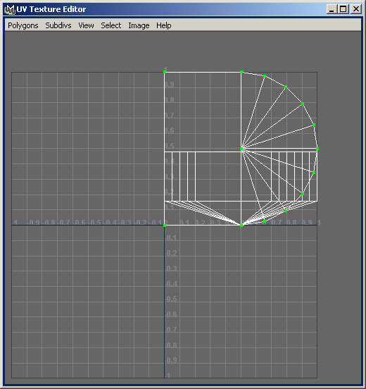
From the Edit Polygons menu, Texture submenu, choose Planar Mapping with options (ie the box to the right). This is one you'll definitely want to add to the shelf! Set the mapping in the Y-axis. Click Project to preview the mapping. Try a few projections in the different axes if you like. When your projection looks like the following, hit Apply.

Now open the UV Texture Editor from the Window menu.

The axes in the editor show UV co-ordinates. These are scaled co-ordinates that your texture will use. Whatever size texture you apply to your model, the bottom-left corner of the image will have co-ordinates (U = 0, V = 0) and the top-right corner will be at (1, 1).
These normalised co-ordinates are used so that you can freely change the image's resolution (and hence actual pixel dimensions) without having to redo your UV map.
As it stands now, any texture applied to the select face would be mapped in such a way that the top-left corner of the image was at the bottom-left corner of the face, the top-right of the image was at the top-right of the face (although you wouldn't see it as the face doesn't fill the UV space!) and the image was rotated 90 degrees anti-clockwise. The picture below shows what I mean. Please note that this is a doctored Photoshop image, not an actual Maya render.

Later on we will make an image and map it to the UV space where Martin Brenner is now. When you fit meshes to skins, you drag UVs about to define how the mapping works. Since we're fitting our skin to the mesh, we're going to arrange the UVs the way we like them first.
There's no point doing anything with only one planar mapping though, so let's first of all move the newly mapped UVs out of the way (so they don't obstruct our view of the others). In the UV texture editor window, select Convert Selection to UVs from the Select menu. You could also right click to change the selection mode to UV then draw a selection box around the whole map ... but why do things the hard way?

That junk behind our nice mapping is the rest of the model. Don't worry, it isn't selected! This is why I said we're going to move the mapping out of the way for later. Press W or choose the Move Tool from Maya's main window to bring up the move manipulators and shift the selected UVs out of the top-right corner of the window. It really doesn't matter where you put them as long as no UV lies in the (0, 0) to (1, 1) box.

Now let's apply a map to the other faces of the chest. The procedure is exactly the same. First we select the faces of one side:

Then we apply a planar mapping (in the Z-axis for this particular face):

And we move our UVs out of the way so they don't obstruct our view of the next face:

Our chest has five faces so wash, rinse, repeat...

To make our lives easier, let's rotate the UVs so the faces face the "right" way up. There are several ways to do this. And coincidentally we have several faces that need rotating...
The first and easiest way is to use the Rotate Tool (hotkey E) to rotate a selection of UVs. The problem with this is that the rotation will not be 100% accurate. Your 90 degree rotation will actually be 89.999876 degrees or something. Whether this is a real problem is debatable.
Next up you could find your projections in the Channel Box (Menu: Display / UI Elements / Channel Box). Each projection appears under INPUTS and is named polyPlanarProjx for some x. You can rename them here by clicking on them and typing a new name ("front UV map", for example). In the image below, I highlighted the first projection we made, polyPlanarProj1, then used the Show Manipulators Tool (hotkey: T) to display the mapping.

Underneath the boldfaced component names are the projection's attributes. You can type the desired rotation directly into the X, Y or Z value boxes. Switch back to the UV Texture Editor to see the result.
Finally you can use MEL to edit your mapping. The command you want is
polyEditUV -a <angle> but I said I wouldn't talk about
MEL...
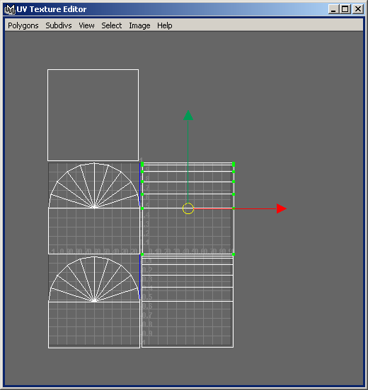
After arranging all the UVs we end up with something like the following:

Now, we know that each UV set represents more or less the shape of the face it's mapped to. Therefore we can visualise the sides slotting together in the way you would build up the faces of a cube. Look at the rounded face in the bottom-left of the image above. Call that the "front" of the chest. In fact it may actually be the back. Doesn't matter; this is only for visualisation purposes. If that face is the front of the chest, the face to the right of it would be the left side of the chest.
To see this, hold two floppy disks or something in front of you with the label facing towards you. Hold one in your left hand and one in your right. The left disk is the front face, the right is the other one. Now turn the disk in your right hand so the label faces to your right.
Now you can see why the righthand face is the "left" side of the chest. You can also see that the two faces share an edge, as the two UV maps appear to in the picture. But look what happens when I choose to select by edge and click the left edge of the face on the right:

Oh dear. The faces are sharing the wrong edge. We'll fix this in the next section.
Of course, it might be that your UVs are all mapped nicely. For the sake of the tutorial, go back and mess some up :)
| intro | part 1: Setting the layout | part 2: Editing basics | part 3: Vertex manipulation | part 4: Face manipulation | part 5: Materials, texturing and UVs - (i) | part 6: Materials, texturing and UVs - (ii) | part 7: Materials, texturing and UVs - (iii) | part 8: Final notes |